

A fracture nomenclature system should be easily understood, should be widely accepted, and should allow accurate communication of ideas and information between geoscientists. For use by petroleum geologists, it should also imply something about the potential effects of a fracture system on reservoir plumbing. Here we will present some of the terms that are applied to natural fractures, but we will focus on a classification system based on the mechanical origin of fractures that is in general use.
Some caveats:
- All classification systems are artificial. They are superimposed on structures that are not naturally binned and that occur in spectra of forms with transitional structures between the most populous classes.
- It is possible to fracture rock in one mode, then to reactivate the fractures within different stress systems, resulting in compound structures with ambiguous characteristics.
- It is also possible to fracture strata that were later deformed so that the present fracture geometry no longer reflects the original stress system.
Such complications can often be accommodated with modifiers such as “hybrid,” “mixed-mode,” and “oblique-slip” for fractures.
Definitions
“Fracture” is a generic term for a mechanical discontinuity in a rock. The discontinuity is typically planar, and it is commonly associated with a loss of cohesion in the rock across the fracture plane. Fractures are brittle to brittle-ductile strain- accommodation structures that develop when rock is subjected to a stress anisotropy greater than its strength.
A common alternate term for fracture is “joint.” Both terms were borrowed from general English vocabulary. We prefer “fracture,” which implies a break in the rock, whereas “joint” comes from the verb “to join” and would seem to imply a connection rather than a break between two rock masses. “Joint” is commonly paired with the term “vein” to indicate that a joint is mineralized, thus “vein” is a second term for the same mechanical structure, but altered by a chemical process.
Different fracture nomenclatures have been used by different disciplines, by different authors, and by those doing fracture work variously in the laboratory, on outcrops, and in the subsurface. Nomenclatures have been constructed on the basis of characteristics such as geometry (for example, dip angles), relationship to structure (cross-fold versus fold-parallel), mechanical origin (extension versus shear), or electrical signature (conductive versus resistive). The term “fracture” is applied to seismic traces tens of meters in height by geophysicists, and to structures measured in tens of kilometers along mid-ocean ridges by tectonophysicists. Nelson constructed a four-fold fractured- reservoir system based on the ratios of fracture permeability and porosity to those values found in reservoir matrix rock.
Fracture Types
Mechanically, two basic types dominate fracturing in rock at reservoir scales:
- Extension fractures, also called Mode I fractures, form when opposing fracture walls move away from each other in opposite directions normal to the fracture plane.
- Shear fractures, or Mode II fractures, form when opposing walls move in opposite directions parallel to the fracture plane.
“Joint” and “vein” usually imply a geometry suggesting an origin in extension, with no counterpart designator for a shear fracture. Some authors note the possibility of rotational shear between fracture walls and call these structures “Mode III fractures.” “Mode IV” fractures, also called “compaction bands,” are tabular zones formed when fracture walls moved towards each other, collapsing porosity. Mode III and IV fractures are rarely reported from reservoirs, but they are difficult to identify in subsurface fracture datasets.
Extension Fractures
The orientation of an extension fracture is controlled by the in- situ stresses: fracture propagation follows a plane defined by the maximum and intermediate compressive stresses at the time of fracturing; that is, the plane is normal to, and fracture width opens against, the minimum compressive stress. Because the weight of overburden strata typically provides the maximum compressive stress in flat-lying strata, the maximum principal stress is typically vertical, most extension fractures are therefore vertical planes, and coincidently, most extension fracture sets are normal to bedding. Extension fractures can form as inclined planes if the stress system is tilted in more complex structural settings.
Extension fractures form as sets with parallel strikes. Younger fracture sets that formed within different stress systems can be imposed onto older sets to form a fracture system of intersecting sets. Most “regional” and “tectonic” fractures – mechanically ambiguous terms based on geographic distributions or relationships to structure – are extension fractures.
Rock is typically both weak and brittle, being susceptible to fracturing under stress magnitudes less than prevailing tectonic and gravitational forces, so almost all strata of interest to the hydrocarbon industry are fractured to some degree. Note, however, that the term “tension fracture” is a mechanical inaccuracy: the tensile forces that easily pull rock apart in the laboratory to create true tensile or tension fractures are non-existent in the subsurface, except perhaps at the tips of propagating fractures. Other than in the laboratory, nearly all structures called “tension fractures” formed in extension (an unfortunately similar-sounding but significantly different process), by dilatancy of a rock mass, within stress systems that were compressive in all three directions. Parenthetically, very few reservoir fractures originated as “hydraulic injections” – such fractures are not common and have distinct characteristics.
Extension fractures commonly terminate at mechanical heterogeneities created by intercalated ductile lithologies, thus many extension-fracture sets are strata-bound and confined to, or at least better developed within, the more brittle layers of a sedimentary sequence. Extension fractures are typically taller and more widely spaced in thicker beds, and they are less planar in heterogeneous lithologies such as conglomerates.
The faces of extension fractures can be ornamented with diagnostic plume structures and arrest lines that formed during propagation, and the terminating fringes can display twist hackle. These features are not universal: they rarely develop in coarse-grained rock, they can be obscured by mineralization, and they can be removed by dissolution.
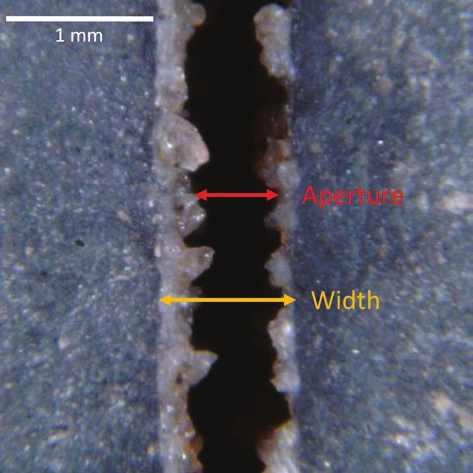
Fractures provide pathways for fluid migration, and the minerals dissolved in those fluids may be precipitated within the fracture widths between fracture walls (figure 1). Fracture apertures can remain as void space within incompletely mineralized fracture widths. Acidic fluids can dissolve and remove earlier mineralization and even some of the host rock, leaving large, irregular apertures (figure 2). Widths can be used to determine percent strain accommodated by a set of fractures, but the ability of fluid to flow along a fracture is determined by the openness and irregularity of its aperture. It is typically easier for fluid to flow through open fracture apertures than through the matrix, but the overall direction of flow in reservoirs is controlled by pressure gradients, not fracture strike.
Single sets of parallel extension fractures can create horizontally anisotropic permeability in a reservoir, with some reported fracture-controlled kH:kh ratios exceeding 1000:1. Such fracture- permeability systems can be exploited with horizontal wells, and must be considered when injecting fluids or drilling infill wells. Since they are commonly strata-bound, extension fractures commonly contribute little to vertical flow within heterogeneous reservoirs.
Shear Fractures
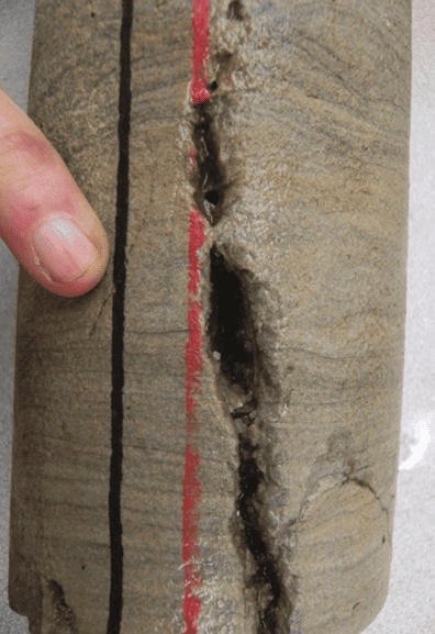
Shear fractures are a more ductile response to the imposition of stress anisotropies on rock. A rock can be somewhat ductile due to its basic composition (for example, most limestones are more ductile than most sandstones), and any rock becomes ductile under the high temperatures and confining pressures at depth unless the pore pressure is also elevated. Unlike extension fractures, shear fracture planes form at angles oblique to the three compressive stress axes and are inherently critically stressed. Single sets of intersecting conjugate shear pairs that formed in a single stress system (figure 3) have better interconnectivity than single sets of extension fractures. Again, shear fractures formed when all three stresses were compressive: tension was not present in the rock.
Conjugate shear fractures have three ideal orientations: Xs standing upright, Xs lying on their sides, and Xs lying on their backs. Orientation is controlled by the relative magnitudes of the vertical and two horizontal compressive stresses during fracturing. Conjugate pairs can also develop unequally such that larger, widely spaced faults are complemented by more numerous but smaller, opposite- dipping antithetic shear fractures. Shear fracture widths are typically more irregular than those of extension fractures due to offset topography (“asperities”) on the fracture faces. Shear fracture faces can be ornamented by slickensides, striations, lineations, and gouge, and by congruent or non-congruent steps. The type of ornamentation depends on the amount of offset, and on the magnitude of the compressive stress normal to the fracture plane during shear. As with extension fractures, the widths of shear fractures can be modified by mineralization and/or dissolution, filling or enhancing fracture widths and degrading or enhancing conductivity along a fracture aperture. The faces of many shear fractures can be altered or even somewhat metamorphosed by the shear during offset, inhibiting fluid flow from the matrix into a fracture aperture.
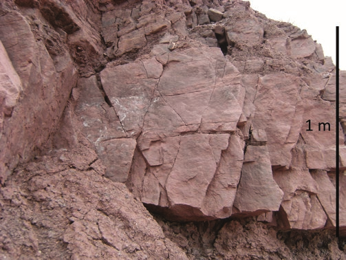
Deformation bands, also called “shear bands,” are a variety of shear fractures where offset is accommodated by compaction and grain crushing within narrow, tabular shear zones rather than along discrete planes. Shear bands form permeability barriers within high-porosity, poorly-cemented strata, and conjugate pairs (figure 4) can compartmentalize otherwise good-quality reservoir rock.
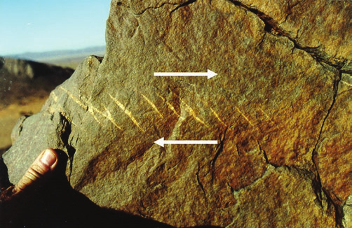
A bit further into the ductile range of the brittle-ductile transition, a rock mass can accommodate shear as trains of short en echelon fractures (figure 5). The individual fractures are short and fat, pinching out abruptly. These extension fractures within shear zones have been called tension gashes or gash fractures. The width of the train of gashes defines a zone of shear, which can narrow as deformation progresses, bending early gashes into “S” shapes. Scattered trains of gashes can form with conjugate orientations although not always as directly intersecting pairs.
The term “fault” is commonly used for larger shear fractures. Some authors suggest that any shear plane should be called a “fault” and that smaller shears with limited displacement should be called “microfaults.” We are loathe to replace “shear fracture” with “microfault” due to the additional deformation, including folded or offset bedding in the adjacent strata, and fault gouge or breccia (sometimes called “fault rock”), that is usually implied by “fault”.
Effectiveness
Fractures rarely contribute significantly to reservoir porosity, but their effect on reservoir permeability can be substantial. In addition to the matrix permeability, system permeability depends on individual fracture parameters such as aperture sizes and the permeability across fracture faces, and on the fracture network characteristics such as fracture spacing and interconnectivity. Systems of shear fractures are typically better interconnected than extension fractures since shears commonly occur as intersecting pairs, and because they are more likely to cut across bedding. Single sets of conjugate shear fractures can be as effective as two superimposed intersecting sets of extension fractures. However, if offset has created slickensided fracture faces or filled fracture widths with gouge, shear fractures can be barriers to flow.
Conclusion
Recognizing and naming fracture type is the first step in estimating the effect of fractures on reservoir plumbing. Extension and shear fractures are the most common fractures in reservoirs. These two basic terms indicate different mechanical origins and have implications for reservoir plumbing. The terms are easily modified with descriptors for characteristics such as geometry, sense of offset, or degree and type of mineralization, to describe common fracture variations. More information can be conveyed with less ambiguity using this nomenclature than with historical terms such as “joint,” “fissure,” “crack,” or “vein.”